


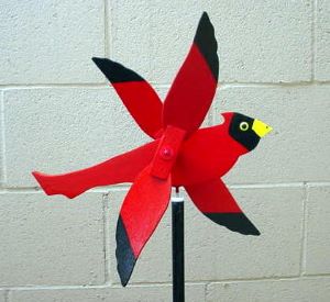
This is what I’m calling a Cardinal Windspinner type of whirligig. I am in the process of making one, and have created and posted a few drawings showing how I plan to make it. I will post a few pictures of my finished product after painting, etc.
This picture is from a creative commons website. It was the coolest looking bird of the ones I’ve seen there, and it is the one I will use to make drawings and a pattern from. I am going to be building this whirligig partially from instructions shown in Anders Lunde’s book, “Easy To Make Whirligigs”, and from other online sources. I would like to mention also that these pages contain affiliate links, so if you were to buy something, I would get a small commission (at no extra cost to you).
Ok, there are a few types of bird whirligigs, and I’m going to make the type that is shown in the above picture.
For a whirligig like this, the body should be made from 3/4″ solid wood (hardwood lasts longest, if you have it). The wings will be made of 1/8″ plywood, and the wing bases will be cut from 1/2″ x 3/4″ x 1-1/2″ solid wood.
The wing mounting hubs (which are underneath the wings) will be made from 3/4″ x 1″ solid wood. The purpose of these mounting hubs is to space the rotating wings away from the body.
This is what the whirligig will look like when viewed from the front :

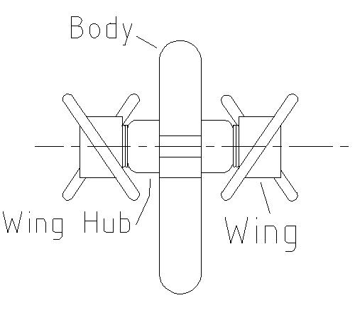
So if you held up the windspinner and looked at it from the front, this is what you would see. The wings would form a “V’. If you view the whirligig from the back, the wings would form an upside down “V”.
Between the Wing Bases and the Wing Mounting Hubs, I will use several plastic washers. The lines on the body show the beak position and the where the head ends.
When this whirligig operates, the wings each spin in opposite directions. Also, I haven’t shown it here, but some whirligigs like this have a slight taper built into the mounting hubs. If they are slightly tapered at the top, the paths of the wings will be slightly angled when they are spinning. But this is optional.

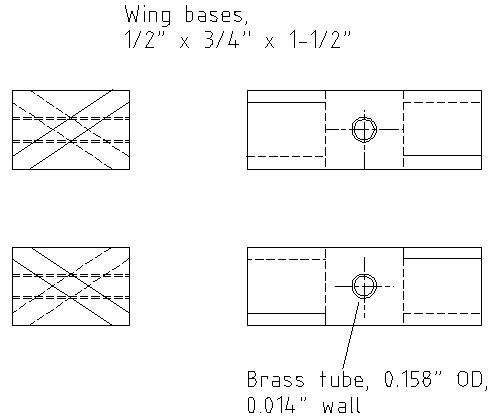
So here’s what the Wing Bases look like. These are the parts that hold the wings in place. There is a left hand and a right hand, which is why they cause the wings to spin in opposite directions. Each end has a 1/8″ wide groove cut diagonally to slide the wings into. The wing slots are shown here at 1/2″ deep and 1/8″ wide.
Here are two ways to make your wings so they swivel. Of the two methods, using a bushing or bearing will always work better over the long run.
1) You can use a brass bushing on the inside of the wing bases – I am using K & S precision metals 5/32″ or 0.158″ OD, 0.014″ wall brass tubing (0.128″ ID) as bushings for the wings, and 1/8″ OD, 0.014″ wall brass tubing as an axle for the wings. These sizes of brass tubing can be bought at most hobby shops, or online, if you aren’t close to any hobby shop. The important thing is that the two sizes of tubing telescope into each other (one size sleeves inside the other).
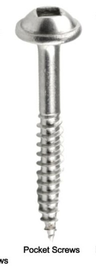
2) If you want to, you can use a bare hole through the wing bases. Size your hole/drill bit to fit the mating screw (the screw that holds the wings on). For the mounting screw, use a wood screw with a smooth upper shank, like the one shown.

The wings will be glued/epoxied into each wing base. Some of the longtime whirligig makers pin their wings in place using a wooden dowel. This is not absolutely necessary, but will make your wings last a little longer when they’re out in the weather. This method is shown here in George Heyduke’s video: https://www.youtube.com/watch?v=VWxhdWJWFNg/ .
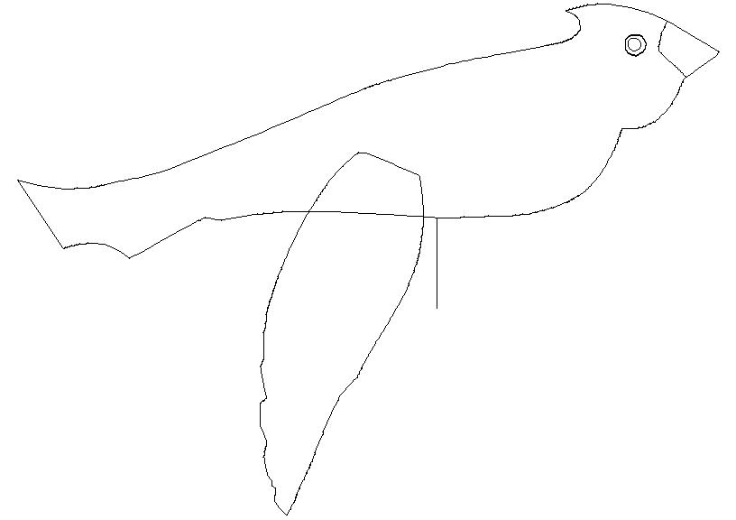
Just below is a tracing of the Cardinal body and a typical wing. If you can scale this and print it out as a pattern, the body should measure approx. 8-1/2″ in length, and the wing assembly should be approximately the same. If you can’t find any 1/8″ wood for the wings locally, you can buy some 1/8″ ply pieces here. After cutting out the body and wings, sand out all the rough spots to make the outer profile smooth.
The finished wing assembly should measure approx. 8-1/2″ in length (two wings and a wing base). If the wings are slightly longer or shorter, that should be ok. The wings can be glued into the wing hub slots with wood glue or epoxy if you have it. After the wings are final assembled, its important that they be balanced. When given a spin, each wing should spin smoothly and not have a heavy spot that swings to the bottom after it finishes spinning. If one side of the wing always settles to the bottom, sand that heavy side until the wing stops in a random location each time. Proper balancing will eliminate vibration, wear, and will allow your wings to spin in a very light breeze.

Now you will have to determine the pivot location, so the whirligig can be properly mounted. To do this, first complete sanding of the body. Put the wings on, and balance the finished sanded body on a round object, such as a dowel or pencil. Make the body sit level on the pencil and find the balance point. Mark its location on the body with a vertical line. This is shown here as the rear most line.


For the wing pivot point, mark a vertical line approx. 1/4″ forward of the body pivot line. On the upper part of the cardinal body, mark a spot along the wing pivot line. Mark this point somewhere on the upper half of the body, but also on the wing pivot line. It is the point where the wings will be screwed on.
The wing mounting hubs should be attached so that the wing attachment screws will be located along the wing pivot line (the line drawn 1/4″ forward of the body balance line). The wings can be located along that line, anywhere on the upper half of the Cardinal body. You can glue and screw the wing mounting hubs onto the main body so that the wing mounting screws are located where you have previously marked the wings to be mounted. Use a smaller drill bit to drill pilot holes thru the mounting blocks for the wing mounting screws. If you are using the same brass tubing as I have used (as a sleeve for the wing bases), you will need to use a wood screw with a shank diameter of 0.120″ or less. You might want to use plastic or nylon washers between any parts that will rub together.

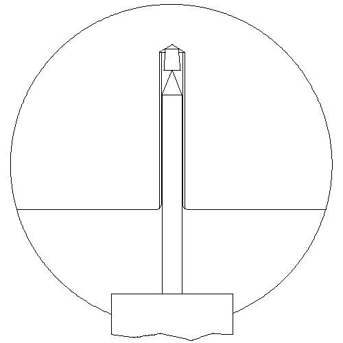
This is what the mounting pivot should look like. I have shown a 0.157″ dia. hole drilled into the Cardinal body (drilled up into the body at the pivot point).
In the deepest part of the hole, I have shown a finishing nail head, which has been cut off and inserted into the hole. The purpose of this part is to provide a solid surface for the pivot point to rest and pivot on (you can also use a BB, a larger nail head, or a steel ball bearing here).
Then I have shown a piece of 0.138″ OD/0.014″ wall thickness brass tube, also inserted into the pivot hole, and cut so it is flush with the lower part of the body. There are alternate mounting methods where the insert protrudes from the body, so whatever you feel comfortable with. I am using brass tubing because that’s what I have on hand. You can find this at most hobby shops, or maybe even somewhere like “Metal Supermarkets”. If you would prefer to use a plastic bushing here, Home Depot or Canadian Tire have plastic or nylon tubing or bushings, that you can use here as a bushing. Just make sure you can fit a nail or whatever you plan to use into the ID of the bushing. During final assembly, lubricate the mounting pivot.
The final piece to mount the Cardinal is a nail, pin, or piece of rod, with a 0.120″ dia. (or sized to fit your insert). which is then fastened into a dowel (broomstick, or…) and points upward. The whirligig rests on the point of the nail/rod that makes up the stand for the whirligig.
So after finishing up to this stage, the whirligig is ready for paint. The body can be painted using the lines shown on the body tracing diagram. Ensure that there is no bare wood showing anywhere after paint.
And your whirligig should be finished at this point, except for finding a place to mount it.