
This is my version of a woodchopper whirligig. This is approximately what you would see from the side. This is a basic whirligig that is about as simple as you can get. I have added a few drawings here to show how I intend to build it. The first is a diagram showing how the main body would go together.
This is the main frame for my woodchopper whirligig. The main frame is made from a wooden piece 3/4″ thick x 2-3/4″ wide x 15″ long. As shown in the diagram, the top edge is slotted to accept the drive rod. In my case, I have made the drive rod slot approx 3/16″ deep and 3/16″ wide (approx 0.180″ x 0.180″). The rear end of the main frame is also slotted to accept a 1/8″ plywood tail. You can find some 1/8″ ply here.
I have shown 1/8″ dia steel rod to be used for the drive rod. This can be bought from Home Depot or somewhere like Canadian Tire, etc. If you are not close to any of these, you can have some delivered here.
So this is how the prop is constructed. In this drawing, I have only shown the upper and lower blades. For the hub, I used a 1.5″ cube of wood. The hub is slotted on four sides so the blades slide in.
The hub is drilled through the center to accept a 1/8″ drive rod. The drive rod is bent back and the hub is drilled to also accept the bent over section of the drive rod.
This is a tracing template for the woodchopper figure. It should be sized at approx 8″ tall to print it. I’m not sure how large or small it will be when printed, but you should try to scale it for a height of 8″. The figure is formed from 3 parts – The upper body is cut from 3/4″ wood. It starts at the curved line that goes across at the crotch area and goes up from there. The left and right legs are cut from 1/8″ or 1/4″ plywood. On the finished whirligig, the legs end at the figure’s waist. I have included extra lines to help visualize and paint the chopper figure. So, the main body is made from 3/4″ thick wood, and is held in place by the left and right legs. The upper body pivots at the hole near the hip area. I might change a few things as I’m building this unit, but I will add any changes to this drawing as they are made.
The legs overlap the frame and are glued and screwed onto the main body about 1 to 1-1/2″ below the top of the frame. The legs are screwed onto either side of the 3/4″ main body. If you’re having problems finding 1/8″ plywood for the prop, tail, and body parts, you can have some delivered from here.
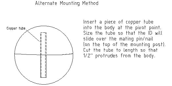
The final step is to assemble the whirligig, and locate the balance point and the pivot point. The balance point can be determined by balancing the whirligig on a dowel or round object. Mark a vertical line on the body at the balance point. At another point an inch or two forward of the balance point, mark the location of the pivot point. I am suggesting a pivot point location well forward of the balance point so that the whirligig will always point into the wind. At this point approx 2″ forward of the balance point, drill the frame to accept a nylon, plastic, or even brass insert (you can insert a copper tube here, as an alternate to these types). This insert should be sized so that the ID (inner diameter) will fit over a 1/8″ finishing nail or pin. This nail will be located at the top of your mounting post, and should slide into the insert.
Another way of sizing the mounting pin is to use a drill bit sized to fit your insert or copper tube, and drill it into the mounting post. Instant mounting pin.
Painting is especially important so that water cannot be absorbed into the wooden parts. If you are using plywood anywhere, it needs to be coated on all surfaces, or the plywood will swell and delaminate. For the prop, I will be using a spar varnish, since it looks really cool and makes the prop look like a real airplane prop.