
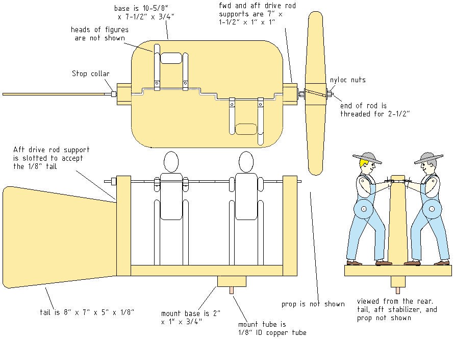
The drawing above shows a whirligig that has 2 men cranking the drive rod. It is complex and I wouldn’t try it as a first whirligig, but if you feel that you can bend the drive rod as shown, then by all means build it. The most difficult part of this unit is bending the drive rod.
The drive rod passes through and is held by the drive rod supports. The supports are drilled through at a slightly larger size than the drive rod. During final assembly, the supports have to be fitted onto the drive rod and then assembled to the base. The man figures are using cable clips to connect their arms, since the arms can connect as a last step in the assembly.
The Drive Rod
The prop drives a 1/8″ dia rod, that is formed as per the drive rod drawing. The drive rod is offset at the figures’ arms by 3/8″, making the wrist joints move in a 3/4″ circle each time the rod/prop makes a full turn.
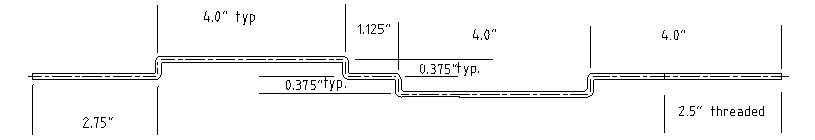
The drive rod is made from 1/8″ (0.125″) dia. steel (or stainless steel) rod. These are the dimensions as I have drawn it.
I believe the hardest part of making this whirligig is getting the drive rod right. If you are planning to make this piece at home, I suggest that you use a method such as this one to add the bends to the drive rod.
How The Arms Connect
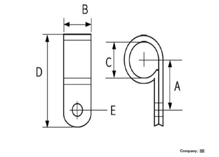
In order for the figures to grip the drive rod, I have suggested using a series of 1/8″ cable clips, because they can be added after the drive rod is formed and is fitted in place. Just below is a manufacturer’s drawing of the type of clip I’m talking about:
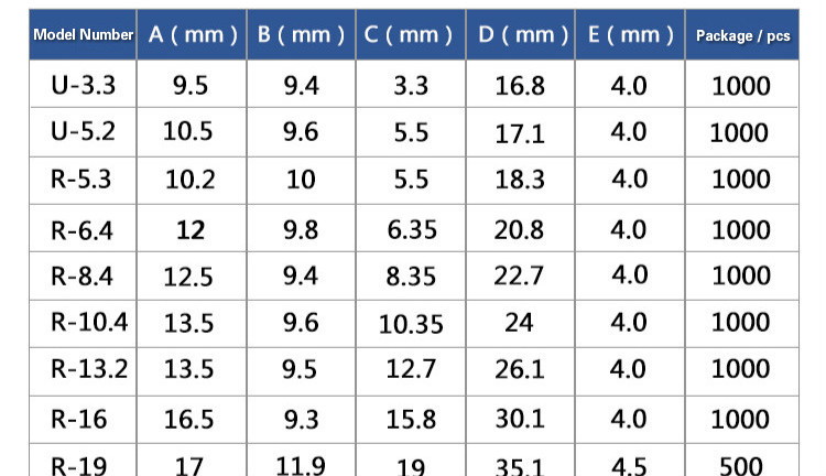
In the images above, I am showing that the drive rod is gripped at the figures’ wrists with a series of cable clips. As per the above table, U-3.3 clips will work with a 1/8″ dia drive rod. (3.3mm = 0.130″, so these clips will accept a 1/8″ or 0.125″ dia rod).
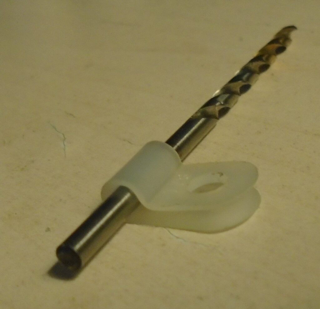
I have a shot of a 1/8″ cable clip just below.. That is a 1/8″ dia drill bit going through it. If you close up the clip around the drill bit, there is a small amount of clearance, so it will hold the drive rod without choking it off. I believe you can find this size of cable clip at Home Depot or Canadian Tire.
The Prop
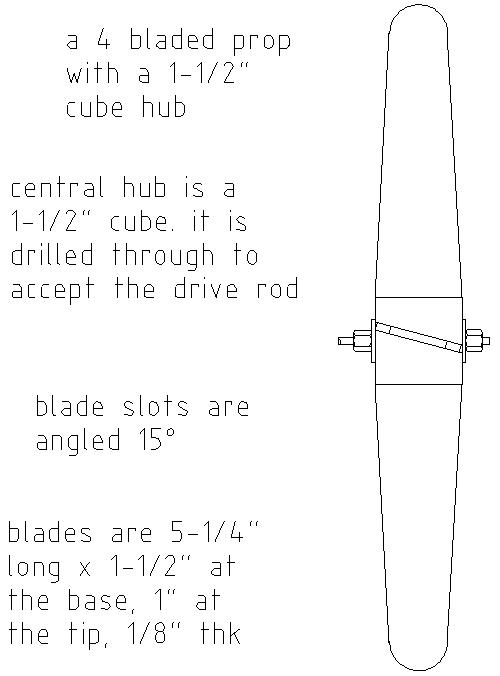
The image above shows how a 4 bladed rotor is put together. The blades fit into a hub, which is a cube, all sides 1-1/2″. The hub is slotted on four sides to accept the prop blades. The slots are 1/4″ to 3/8″ deep, and angled at 15 degrees to catch the wind. The hub is drilled through at the center point to allow the drive rod to pass through.
One Way To Mount The Prop
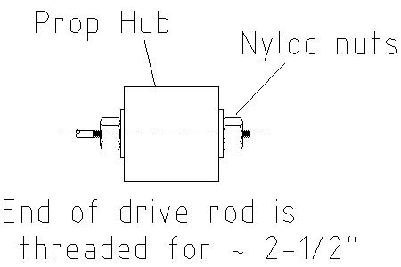
The image below is showing a common method of mounting the prop. The end of the drive rod is threaded for approx 2-1/2″ from it’s end. The prop hub is pinched between two nuts which hold it in place.
A Commonly Used Method Of Mounting A Whirligig
A Commonly Used Method Of Mounting A Whirligig
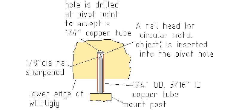
The above image shows a common method of mounting a whirligig. A hole is drilled into the pivot point. A small slug of steel (such as a cut off nail head), is inserted into the hole. This will provide a stop for the mounting pin. A copper tube is then inserted into the hole. The ID of the tube is sized to fit the mounting pin, located on the mounting post.
To determine the pivot point, balance the complete whirligig (without the mount base fitted) on a round pencil or dowel to determine the center of balance. Mark this location with a line across the base, and mark a point roughly 1/2″ forward of the balance line along the center of the base. This will be drilled and will be the pivot point.
Painting The Completed Unit
The final step is to paint all of the exposed surfaces on the unit. Any exposed wood will absorb moisture and swell, rot, and warp., so coat all exposed surfaces to keep the unit in good working condition. This is especially true for the prop blades and tail, if you make them from 1/8″ ply.